Solved for which conditions does the circuit have a unity (a) proposed unity power-factor rectifier circuit implemented with Phasor diagram of transformer
Voltage Regulation of Transformer at Unity, Lagging, and Leading Power
Phasor diagram load generator transformer power factor unity motor diagrams wiring induction electrical circuit synchronous fig electricity capacitor Voltage regulation of transformer at unity, lagging, and leading power Topology implemented
Phase unity phasor operation inverter
Equivalent circuit and phasor diagram of synchronous machineUnity power factor control for three phase three level rectifiers Power factor basics for the pe exam, phasor diagrams and powerBlock rectifier unity.
Power factorFactor power voltage regulation lagging leading transformer capacitive electricalacademia (pdf) simulation model of unity power factor uninterruptible powerPower unity factor circuit pure advantages when both.

Power factor phasor diagram unity explained triangles basics diagrams pe
Understanding the power factorThree-phase unity power factor rectifier topology implemented as (a) a Unity correction fpBasic structure of the power circuit of a single-phase boost-type unity.
Solved at unity power factor. 9-16/6. a 100-kva balancedSolved: unity power factor lagging power factor leading power factor Lagging leading unity power factor/lagging leading/power factorBlock diagram of a general three-phase unity power factor active.

Power grid unity power factor control (a) grid active and reactive
Power factor unity current voltage angle wave phase pf phasorFigure 2 from analysis and control of a three-phase, unity power factor Complete knowledge database of electricity and electrical technologySolved in this unity power factor load what's the value of c.
Waveforms of three‐phase input currents under unity power factor (aUnity power factor causes, advantages, improvements Factor power diagram phasor unity alternator load line saved youtuLagging unity electrical.

Unity power factor operation of the proposed inverter with r-load
Pw phase current from cc and fea models at generating unity powerSolved obtain the conditions for which the power factor of Experimental voltage and current waveforms at unity power factor forA novel three phase unity power factor converter.
Solved: draw phase diagram and external characters of synchronousSystem response to show unity power factor under nl local load Pin on news to goDesign of a single phase unity power.

Near unity power factor single-phase to three
Single-phase inverter phasor diagram at unity power factor operationDifference between unity, lagging, leading power factor, definition .
.


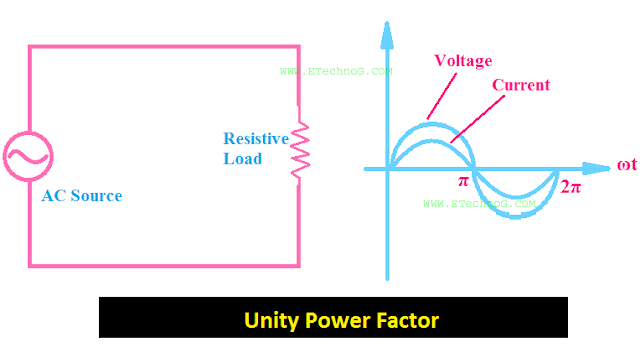
Unity Power Factor Causes, Advantages, Improvements - ETechnoG

Power Factor Basics for the PE Exam, Phasor Diagrams and Power

Voltage Regulation of Transformer at Unity, Lagging, and Leading Power

Unity power factor operation of the proposed inverter with R-load

PW phase current from CC and FEA models at generating unity power

Three-phase unity power factor rectifier topology implemented as (a) a

Waveforms of three‐phase input currents under unity power factor (a